Sunday, December 27, 2009

S.S. VALHALLA Part - 3


Merry Christmas to all.  Hope Santa was good to all.  
Spent a nice long weekend at home with the family, just relaxing and working on trains.    As I've said in earlier blogs I am trying to divide my time equally between building structures and the layout.  I'm proud to report that all the track is down on the Coke Works Branch and it is about half wired for power.  I even was able to install one Tortice switch machine.   I also repainted the backdrop in this section - just the sky - still need to do the clouds.    I'll take a photo of the branch line panel when I'm finished with things.  
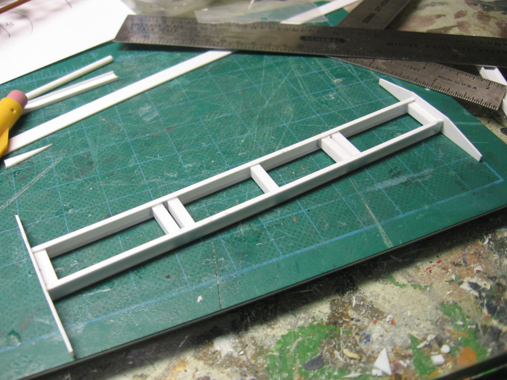
I also continued working on the SS Valhalla freighter.   This is a completely freelanced ship design.  The only photos I am working off of are a few from a Model Railroader website feature I printed out on marine modeling - and an article from the same magazine featuring a coal ship on the Severna Park layout.   The marine modeling feature had a few photos of a freighter in HO scale that was built from a kit - I looked up the kit and it was way too expensive so I chose to scratchbuild.  There were features on both the models that I liked and am incorporating them into my model, plus some other features I picked up from maritime books,..etc.    My freighter represents a very smallish, WWI vintage freighter, still in use in the 50's but for hauling pig iron to third world nations and bringing back iron ore.  (Colonialism at its finest)   This will had some operational interest - moving materials and products between the port and the furnaces.    I started to add some bracing to the bulwarks throughout the ship using styrene strip.  The rest of my work focused on the superstructure.  Freelancing this as I go, I'm pretty pleased with the overall proportions.   I intend to make some masters of hatches and other features and cast them in resin.   The tank behind the pilot house is a water tank for drinking, washing, and cooking.   Most of the superstructure was built out of .040 sheet styrene.  The closed railings are .020 sheet.   The stack is 7/8" tube  with a 1" base.  

Tuesday, December 22, 2009

S.S. VALHALLA Part - 2


Working from the MDF core, I laminated the decks and bulkheads with sheet styrene, taking time to cut out a few port holes first.  I then added the sides.  The sides are .040 styrene.  There are five panels altogether.   Some of the panels form the high railings of the ship so careful layout was necessary.  I also intend to portray a riveted steel hull.   A real ship would have overlapping panels joined with rivets - this is a bit complicated to do in 1/87 scale so instead, taking a trick from the Severna Park Model Railroad group I will use applied strips with rivets embossed on them.  

ELECTRIC MELT SHOP - Part 11


Well the week started off with a decent sized shipment of discounted Plastruct - mostly tubing, ladders, motors, and lots of warren trusses - thanks to a model railroad friend that has an inside track.   I used some of the new materials to continue work on the Electric Melt shop - adding a truss frame on the side and 1/4" channels and I-beams to the framework.  I still need to add quite a few diagonals but it's getting there.

Sunday, December 20, 2009

General Update - December 2009


I've mostly been working on the actual railroad in the past week or so.  The scratchbuilding as become sort of a catch-22 -  I spend a lot of time building things but then don't finish the last few steps and the painting/weathering - why? - primarily because of the state of the actual layout - anything I finish will have to be moved several times for things like painting and ballasting the rails, scenery, laying the actual rails, backdrop painting adjustments,...etc.    So my goal is to start finishing the trackwork, electronics, painting and ballasting the track and some basic scenery items in specific sections so then I can finished structures and start to detail specific scenes.   I also need to finish some construction on the layout room - primarily the ceiling.  I have an old house with tongue and groove flooring directly on the joists - this means that dirt and dust works its way through the floor and eventually onto the layout.  I have been building sections of plywood ceilings and valences directly over the layout to prevent this.  I would have liked to build a drop ceiling spanning the entire room but being an old house and being 6'3" tall, I wouldn't be able to stand up.  I literally need to stand between the joists while working on the layout.    This all doesn't mean I won't be working on scratchbuilding too - I will be doing a bit of each.  I will include in the blog some things I am working on as it would probably be of interest also.  

What I am calling the Coke Works Branch had the track on it partially ripped up as it had been originally intended to be part of a city for an earlier model railroad.  For economic reasons I elected to keep this branch Code 70 track, reusing some of the old Shinohara Track and adding some new Micro-Engineering flex track. I am of course a bit nervous about these old turnouts and DCC but I've talked to a few people that have said the problem is overstated - we will see I guess.   As part of the layout work, I built the frames for four control panels - one for the main , and one each for the port, the blast furnaces, and the coke works branch.    Each panel will get a Power Shield breaker.    In the course of the friday night operating sessions I have been attending I've used both ground throws and switch machines and feel that while both have their advantages, the machines are the way to go for my situation.   The level of finished detail that I intend will include a lot of wiring, piping,...etc.  that would probably get damaged with ground throws -  machines, although  an expense, will prevent damage.   I will use Tortice Machines throughout.    One thing I am scrapping - DCC control of switches.  I originally intended to use this and already have a Digitrax decoder that works four machines.  It might be something to retrofit later, but from an operational standpoint it would be confusing for someone new to the layout and also, you can't throw switches from the NCE utility controller.    I've posted a jpeg of my first draft of my panel design for the coke works branch.

Wednesday, December 16, 2009

HIGH LINE Part 4


With the work on the ore transfer car mostly complete I started thinking about getting back to the highline so it would have somewhere to run.   As I think I stated in the past, the construction is pretty straightforward, it just is repetitive.  I can cut out the parts for and build, maybe four bins in a night.  At this point I have built 18 bins.  Because of my continued issues with styrene warpage I am going to build the highline in three sections of 20 bins each - so you can see, I have my work cut out for me.  I will also need to build a short spur at the one end for the boiler house (to deliver coal to if needed)  and a bridge at the other section.

Sunday, December 6, 2009

ORE TRANSFER CAR - Part 7


A few finishing touches to the ore transfer car end up making for four or five hours work.  Added a lot of pivot pin ends,....etc.  basically small diameter styrene rod chopped thinly and glued on.  I also added the brass ladders and steps.  Built an air tank for the one platform and added the trolley poles.  Probably a bunch more stuff but it's mostly complete.  I have to figure out how to make a number plate for the ends and then paint and weather the car.  Overall this build was pretty complicated, primarily due to the wacky compound angles in the hopper.   I'd rate myself a 6 out of 10 as far as satisfied with the result.  There are a few pieces a little out of wack - whether this is warping styrene or bad measuring, it's hard to tell.  I probably will build a second car at some point, way down the road, and hopefully do a bit better.

Saturday, December 5, 2009

ORE TRANSFER CAR - Part 6


Spent four hours or so working on minor details - getting close to a finished product.   The brake gear was a bit of a pain modeling, but I felt that it was important to include visually.  I also mounted the trucks with screws - they turn but the wheels are fixed.    I also added the wide rim on the front and back top edge of the ore hopper - they are installed on a downward angle.  Side plates of .020 styrene were added to the platforms at each end, as well as railings (Tichy pipe rails).  I built the doors using .020 styrene and scale 1x4 styrene strips.   The doors are smaller than most prototype doors so commercial castings were out of the question.   What's left?  traction motors, door operating mechanisms, an air tank, the trolley poles, front windows, number, headlight, and a few other details.  Can't wait to paint it.

Thursday, December 3, 2009

ORE TRANSFER CAR - Part 5


Doors -  The door assembly is comprised of a fixed panel on top and a moveable panel under - four assemblies total.  The doors are activated by a motor or mechanism concealed in the space between the cab and the hopper end wall.   The fixed and moveable doors were built from .020 sheet styrene and .030x.100 strips and a few .100 I-beams.  I still need to add hinge pins and spacers and some sort of arm to trip the door, whether I actually build the activator or not.  

ORE TRANSFER CAR - Part 4


Trucks part two -  Work continued on the trucks using a variety of styrene strips and shapes to build up the truck frame details.  So far I'm pretty happy with the results.  For this I am primarily using pictures.  The trucks shown in the drawings that I have are different, so they must have changed them out at some point.  I still have to add traction motors and a drive train (waiting on a Plastruct order for the motors), and also the brake gear.

Tuesday, December 1, 2009

ORE TRANSFER CAR - Part 3


Before I continue with this series I'd better give an idea what was the purpose of this machine for those non-steel folks.   The ore transfer car that I am modeling is based on the prototype machines used at Bethlehem Steel (Lehigh) to transport iron ore and maybe limestone? from the ore yard/sintering plant to the blast furnace storage bins via the highline.  Each unit was self propelled using electric traction motors drawing power from an overhead trolley wire.  Bethlehem Steel's units were somewhat unique in that they used a wide - gauge track (7' 10" between rails).  Presumably this was so the transfer cars could be larger and carry more ore.  Once over the appropriate bins the side doors would open and the contents of the car would fill the bins for use later in the blast furnace.    See photo of the prototype.
Returning to the model  - I added some 1/16 angle stock to the sides of the hopper to simulate the ribs.  Also, I started construction of the trucks.  You can see how I built the wheelsets and set them for the wider gauge.  I used .040 styrene for the side frame base and styrene tubing (round and rectangle) for the hubs.  More to come on these.

Monday, November 30, 2009

ORE TRANSFER CAR - Part 2


There is not a right angle in the whole mess that makes up the hopper assemblies.  I cut and fit the hopper end top pieces and then built the bin dividers.  After this I removed the portions of the original hopper bottom plates to give it that sectional appearance.  I also added some .030 strips to make the hopper sill plates 

Sunday, November 29, 2009

ORE TRANSFER CAR - Part 1


I finally was able to find a copy of plans for the ore transfer cars at Bethlehem Steel.   I had considered building it off the photos, however, it is a bit more complicated than it would first appear so I am happy to have the plans.  I printed the plans out on 11x17 paper to as close to HO scale as I could.  It is still necessary to use the printed dimensions where possible as the plans were photographed so there is some distortion.   I might build additional transfer cars in the future (Beth Steel had at least three or four I think)  but for this unit - it will be a static model, and it will be gauged to at least roll on 7' 10" track, just like the prototype.   Another modeler from the Steel Mill Modeler's group - Steel Man Jules, built a well done operational version using a Bachmann GP30 drive.  The car runs on standard HO track with false truck sideframes giving the appearance of the wider gauge.   Since I am building the prototype highline with the wide gauge track I figured I'll stay true to scale.   
Construction on this model started with the main framework - two 3/16" channels with 1/8" square cross bracing.  I used .030x.250 strip for the end plates and the same material cut-down for the floor supports.  I added a .040 deck on each end and then cut and added the bulkheads for the hopper section.  To square up the ends I built the operator cab walls.  As I wanted to keep everything square I didn't cut the doors out of the side walls yet as this would have made things weak.  I will do so after I add the cab roof panels.   Unfortunately the hopper is not just one big box - it has all sorts of crazy angles and is actually four compartments with four operating doors.  To get started with this I cut and fit the hopper ends and the two panels forming the v-shaped bottom.  I filled the space between the bulkheads and the hopper ends with a styrene platform - this is where the machinery that opens the doors is located.   Eventually I will have to cut out part of the middle of the v-shaped bottom, but only after I cut and fit all the remaining panels.  

S.S. VALHALLA Part - 1


I talked earlier this month about my poor judgement in using foam as a core for the A-furnace foundation.  In keeping with this, I tossed the foam core I was going to use to build the SS VALHALLA,  a freighter, in my port area.  Although I hadn't actually added any styrene to this I figured I would end up having the same issues so I built a new core out of layered MDF (medium density fiberboard)   MDF, is a bit harder to shape and cut than foam but I am happy with my results.   If you are wondering about the name of the ship - it's my hometown in New York.   I know, strange name for a town,  and coincidentally (or maybe not) the town is actually a necropolis as the dead outnumber the living by many many times.  The New York Central even offered a special funeral private car from New York City -  might make an interesting operational scenario for the Operations SIG.

Sunday, November 15, 2009

ELECTRIC MELT SHOP - Part 10


Not much modeling to report.  Plenty of model railroading, just not on our layout.  Our friday night operating sessions are something we look forward too, especially Jimmy, after a week of school and work.  We also volunteered to help out at a few of the open houses this past weekend - Jimmy was at the Kade RR and I helped out at the Camden and South Jersey.  It's great to see all the kids that are in awe of what they see, but sadly, most of them probably will never take up the hobby.  I guess there are many reasons for this, but I feel that one of primary ones can be found at home - parents over-scheduling their children's free-time.  When I was young I would say at least 90% of my free time was mine to do as I wanted - play in the woods, ride mini bikes, fish, model railroading, model rockets, building plastic models, painting miniatures, playing games,...etc.    Now society has programed parents into thinking that if their children are idle they will some how miss out on the financially successful life they should be striving for.   Many teachers contribute to this mess - if your child isn't getting A's it's because you are a bad parent and aren't spending 4 hours a night working on their homework with them - of course it couldn't be bad teaching (which there is way too much of) or  politically correct lesson plans from outer space.  What happened to educators educating my child?    Think of all the skills and creative thinking that a 12 year old would get out of a model railroad, unfortunately none of them I guess will help get him into Harvard.   Well I guess we can hope that a few went home and their dads or moms went out and bought some supplies to help them start putting a layout together.   At the open house I was at, only one parent, and believe it or not it was a single mom,  spent around 15 minutes talking about what she needed to do to get started - fortunately the owner of the layout was giving away some old issues of Model Railroader - hopefully those help her.    At 43, the one thing that is wearing thin on me is that way too many people, upon identifying me with this great hobby - (1) tell me about all the Lionel crap they have in some box somewhere and then (2) ask me to affirm their belief that it is worth somewhere between $500,000 and a million dollars .  I wish for once someone would ask me how they would get started with putting it together and getting it running.  
Enough ranting -  
I've been working on the melt shop some more, adding structural elements to the existing model.   A few more things were added to the rolling stand.   I'm excited about my finishing mill - I just need to pick up the additional rolling stand kits.  I was planing on using my hobby allowance this week (I get it every other week)  to order these kits, but I ended up buying the Morning Sun Steel Mill Railroad book  that just came out.  I liked it but I'm not sure it met my expectations totally, especially for the hefty prices on these books.  The coverage was spotty and I got the sense that the author doesn't understand the steel industry as good as he should to write about the railroads that serve it.    I also bought a little paperback on the Pennsy waterfront operations in Jersey City that was actually very interesting.  The author didn't have a vast railroad knowledge, actually I felt he probably wasn't actually a railroad historian either as he identifies the locations well but is very sparse on background info and he doesn't give you the bigger picture of the overall operations.  In one picture he even mistakes the end of a baggage or passenger car for a boxcar.  The pictures are mostly from the Jersey City public library collection and they are very good and for $15 well worth it.  The intention seems to put one of these books together on each railroad in Jersey City.
 

Monday, November 9, 2009

GLASS FACTORY - Part 1


In an earlier post I alluded to a future glass factory project based on the Walther's Electric furnace kit.   The prototype I am using was the Midland Glass facility just outside Matewan, NJ on the Central Railroad of New Jersey.  It was in operation until the mid 1990's when the cost of electricity and NAFTA led to it's closure.  It's primary product was glass bottles.   The facility is pretty large and I have no intention of modeling the entire thing, rather, I am building it as a larger backdrop type structure - I am only modeling a portion of the buildings that fronted the railroad tracks.  This is the interesting portion of the facility anyway and the rest is pretty much just huge boring warehouse type buildings.    The first step is to build two halves of the electric furnace building - I am not using the lower section or the trusses or columns.  Most of the later were used on the Electric Melt Shop anyway.  

A-FURNACE PART 22


New casthouse foundation.   It is built out of 1/2" mdf and is nice and solid.  I re-glued the columns and side trusses back in place on .030 styrene pads.   It needs a little clean up and filling, and I need to define the iron and slag runners better, but otherwise I'm glad I revisited this structure as the old one was actually in a lot worse shape than I had thought.  The solvent based glues I had used, I thought, sparingly, dissolved large chunks of the foam core.  

Sunday, November 8, 2009

ROLLING MILL - Part 1


There should probably be a sub-title for this blog - secondary mill.   I intend to have at least two rolling mills on the layout - the primary mill is going to be located just off the main yard and one secondary mill will be located on the coke works branch.   I am working on the secondary mill first.  The main building is built from two of the old Walther's Rolling Mill kits.   The newer version is actually two of the old building with a roll stand and various other details.   I was able to purchase the interior as a separate kit from Walthers.  It contains all of the interior details from the kit.    Prior to the release of this kit I had purchased some resin castings of a rolling mill and a scale breaker.  These are well done and reasonably priced castings, but they are not complete kits - much needs to be added to complete them.    In comparing the resin mill stands to the Walthers, the resin stands are much larger.   I intend to use these larger stands in my primary mill, and use the Walthers stands in the secondary mill.  Eventually I will be putting four of these stands together.  The photo shows the first stand pretty much complete.  I need to add some additional pieces to build up the conveyors to the right level.  The motor and drive train details, which are well done, need to be truncated a bit to fit in the building and still have one of the tracks useable.  I have sawn off the one motor completely.  This actually is prototypical, as the motors were usually in their own room, to isolate them from the dirty rolling process and to keep them cool.   

ELECTRIC MELT SHOP - Part 9


I'm using styrene strips and structural shapes to beef-up the kit trusses and columns.  I started by applying 0.030x.250 strip under the trusses with .060x.100 horizontals.  I am also laminating the exterior of the columns with 1/4" channel.  You can also see some more work on the crane.

Tuesday, November 3, 2009

A-FURNACE PART 21


Not exactly back to working on A-Furnace but I will be real soon.  One of the things that have been bothering me with this structure was the foundation of the cast house.  I have never been thrilled with its appearance or construction, and I was having problems with warpage that was causing the structural columns to lean out of plumb.   The styrene over a styrofoam core was just not a good idea.   The more work I did on the blast furnace proper the more this would probably bother me, so I figured I better solve this problem now.  I intend to build a new base using MDF and scrap the old one.  I was able to remove intact the wall framing, so I should be able to just reattach this to the new base.    Photo is the old foundation RIP

ELECTRIC MELT SHOP - Part 8


The Walther's October sales flyer had an offer that was too good to refuse - the electric furnace kit for about $30 off list price.  I probably should have bought five or more, but watching the budget I bought one.  The kit will never be built as intended - the parts will be broken up and used for two or three different purposes. -  1) Some of the columns, girder rails, and trusses will be used to extend my existing electric melt shop.  As is, it is too boxy looking, and the extra trusses will add some length too the structure.  I intend to leave the panels off this part of the building as Dean Freytag does on some of his structures where he as finished the interior.  2)  I will be using the wall and roof panels to build a model of the Midland Glass Company - a New Jersey glass bottle manufacturer (more on this in a future blog).   And 3)  I might build a second electric furnace.   The photo shows the melt shop with the extended truss sections.

Thursday, October 29, 2009

ELECTRIC MELT SHOP - Part 7


The few hours I've been able to get into the basement in the past week, have been spent mostly on non-steel tasks - more track laying - decoder installs - starting some scenery - and generally planing things.    I did pick up the Walther's Heavy Duty Crane kit for the electric melt shop.  I actually have three of these on order for elsewhere in the plant.  For the price you get a basic crane assembly that will save a lot of scratchbuilding hours.  It is, as are most Walther's kits, slightly incomplete and under-detailed.   After building the model pretty much per the instructions, I've started to detail the crane using mostly styrene shapes.   In the picture you can see the drive motor, transmission, and drive shaft that was added to the one side of the crane.  I still need to add the electrical contacts for the trolleys along this side and then a walkway on the other.  These simple things add some "mass" to the model.   By the way - these ideas are mostly from Dean Freytag's Cyclopedia.    
A second picture shows a slightly blurry ladle from the electric furnace kit being upgraded with a refractory lining, new trunnions, and a tilting bracket.

Thursday, October 22, 2009

COMICS


Some of you folks that were at the Steel Mill Modelers Meet a few months ago might have seen the USS Joe Magarac comic that John Glabb had a slide of.  I actually have a copy of that comic book, and a second one that US Steel put out.  The Joe Magarac comic is interesting, but the other comic, just titled Steel, is actually an excellent primer on how steel is made from iron ore and turned into a finished product.   These are the covers of both,  and a page from the Steel comic.

Sunday, October 18, 2009

ELECTRIC MELT SHOP - Part 6


Funny thing happened earlier tonight.  I pulled the electric melt shop interior out to add a trestle/floor to carry 30" gauge track and add a few other items, and my son asked what I thought was a stupid question at the time - "Is that going to fit in the building?"   I answered, "of course".  After all, I must have checked the fit at one time - right? - well apparently not.   It was a simple fix - I had to cut off the walkway to the right of the transformer vault and a corresponding amount of foundation beneath.    

One thing I have been doing a lot lately is looking at a lot of electric furnace photos.  From what I can tell, there were two ways of charging them - either by a side door, or by moving the furnace top  to one side.  The top loading seams to be pretty universal after the 1960s and Brandon Wehe makes an excellent bottom discharge scrap bucket that would be used for this purpose.  However, at least at Bethlehem Steel (Lehigh) in the 1950s, scrap and additives were loaded through a side door using conventional open hearth scrap trays or buckets.  It makes sense, after all, the melt shop at Bethlehem was originally an open hearth facility.   I will be using this latter method for two reasons - fidelity to the prototype, and to give a little running room to the 30" narrow gauge track (the electric melt shop is within the blast furnace section of the plant and about six feet or so from the bessemer and open hearth steel facility.)    The idea is that all the scrap prep and loading into the narrow gauge trains will be at one location in the steel making section of the plant.   My narrow gauge system is not just for show but I intend to include it in the operating scheme.
So - tonight - besides the modifications for size reasons, an elevated platform for the narrow gauge track was added and attached to the rest of the furnace assembly.  Also, I worked on the transfer car for the hot steel ladles. 

Saturday, October 17, 2009

Narrow Gauge - Part 6


No more work on the locomotive tonight.  I did begin to rough out a general purpose car that I can replicate pretty fast and cheaply without resorting to resin casting.   It's a basic design using styrene, but it looks pretty good.   After these pictures were taken I added covers to the axle bearings, which improved the overall appearance.  I still need to add some angle or some other structural stuff to the axle bearings to act as additional supports and give this part of the model some more detail.  I also need to pick up some HOn3 couplers for the loco and cars.    The car will hold four seven foot scrap boxes (by Ken Ray Models)  or two 11-ton ingot molds.  The latter might be pushing it as the car has some big overhangs.  Seven tons or less might work better.