Saturday, January 30, 2010

A-FURNACE PART 26


Well, it's official - there is continuous piping from the dust catcher all the way through to the precipitators.   Right now there are two removable pieces so I can take each sub assembly to the work bench for additional work.   There is still a lot of complicated piping left on A-Furnace and in the remainder of the mill.  In my book, it's the large diameter piping throughout the plant that sets steel mills apart from other industries.     The area in the background is going to undergo extensive remodeling in the next few weeks and is the future location of a rolling mill and the bessemer plant. 

Monday, January 25, 2010

GLASS FACTORY - Part 2


After being on backorder from Walthers for a few months, my chimneys came in giving me the incentive I needed to get back to work on the glass factory.   As I said in the first post on this subject, this will be more of a kitbash - some scratchbuilding - but not as much as usual.   I am using a Walther's Electric Furnace kit cut in half, four Walthers chimneys, two conveyor belt kits, and then a bunch of styrene.  The photo shows one of the two furnace buildings (four furnaces in all), mounted on a .125 styrene base with scratchbuilt bases for the chimneys.  They are still a little short for my liking, but nothing else taller is available in brick.  

A-FURNACE PART 25


I installed the two steam powered thermal expansion goggle valves to the gas washer structure.   I started to build the segmented elbows and bends from 1" Plastruct tubing.   This task is actually one of the more difficult things to accomplish - even with the plastics blade in the miter saw there is some chipping, maybe due to cold weather, but I'm starting to think that a better method might be a jig in a small bandsaw with a fine tooth blade.  I've been thinking about buying a small bandsaw to put in the basement on my modeling workbench.    The other technical problem is fitting the piping together properly - the one pipe needs to exit the structure and hit the precipitator complex at the exact same height.  On the other end, the pipe exits and does a few twists and turns and needs to hit the dust catcher at just the right height.  There is a piece in the dust catcher connection that I can adjust to get the height just right, but I have to work from the catcher and the venturi scrubber simultaneously to get it perfect.

Wednesday, January 20, 2010

A-FURNACE PART 24


The steam piping was added to the thermal expansion goggle valve - just some brass rod - .032, strip styrene, and styrene tubing.   I need to file the cut ends of the piping flat.   The second picture shows one of the valves in place on the output side of the gas washer.    For those new to the blog, the gas washer is housed in a large structural framework on the slag runner side of  the A-Furnace casthouse.(part of the structure is a protective wall for the slag track.  This was the second structure that I started working on - at least a year ago.  There are a lot of structural steel elements and walkways to add to it, however, I was waiting to finish the piping.  The hang up with the piping were the two valves that I kept putting off building.   The remaining piping are a series of segmented bends and connecting pipes - on one side the dust catcher, on the other, the precipitator complex (this is a separate blog topic)

Tuesday, January 19, 2010

A-FURNACE PART 23


A recent discussion topic on the yahoo steel mill site concerned goggle valves.  It got me thinking about the many that I need to build as part of the gas cleaning system for A-Furnace (not to mention an undetermined amount for B-Furnace).    Basically, most of the goggle valves for the precipitators are the small electric or manually operated type.  However, there are two larger steam actuated valves on the waste gas piping, before and after the gas washer.    I built these using 1" Plastruct tubing and a variety of styrene disks in different diameters and thicknesses.  They are mostly complete except for the gas piping and control pipes.  I modeled both valves in the open position as they would be with the furnace operating.  

Monday, January 18, 2010

By-PRODUCTS PLANT Part - 10


Work on the primary coolers of the By-Products plant seem like a never ending prospect.  I added the outflow piping today that will enter the building housing the gas exhausters.  Before entering the building I split the pipe and stepped the  size down to 3/8" from 1/2".   Making flanges for the smaller pipe diameter was just a few turns in on the lathe tooling holder.   With all the work on this structure I estimate that I am probably only a little over halfway there as far as detailing goes.  I still have to add extensive water and drain lines, as well as platforms, piping supports, and additional stairs.  
On the tar extractors, I added the posts for the handrails around the top.  I have been using a new method for these individual posts that is another good example of why I'm finding, after 30 plus years as a lone wolf model railroader that it is beneficial to get out and meet other model railroaders and learn how they are doing things.   For the past year or so I have been simply glueing .030x.030 styrene strip vertical, creating the posts for a railing system.  It is easier to do this than it sounds, but as there is only .030 of glue holding the posts to the model, they are fragile.  At this past Steel Mill Modelers Meet, Vince Altiere suggested drilling a small hole (I'm not sure of the drill size I am using, but it's around .030) first and then sticking the glue softened post into it - a method that he uses.  Well it works great and only adds a slight more time to the assembly process, but in a way, even that works to advantage as you can work out any spacing issues that arise, before putting in half the posts.    I added a five foot section of 5/8" tubing to the top of each extractor, and then a smaller, horizontal tube (3/8"), and then finally another, 1/4" tube section.   These are not gas pipes, but rather the high-voltage feed for the extractor.  I connected these feeds to a small electrical box at the base of the model with three .032 conduits.   I finished out work on this structure by adding the 1/2" outflow piping.

Sunday, January 17, 2010

By-PRODUCTS PLANT Part - 9


Added the outtake manifold to the primary coolers.   Work included three additional gate valves, although these valves don't have the extended control arm - just a turn wheel on the valve itself.  I will need to construct a platform for access to these controls.   As pictured the manifold doesn't go anywhere - I will be adding piping between two of the valves that will split the 1/2" gas main into two 3/8" pipes, which will enter the by-products building.  The split was due to connecting to two separate exhausters in this building (they will not be modeled).  From the exhausters the gas would exit the building, back in a single 1/2" tube(modeled size) and then pass through two tar extractors.  I have started construction of these extractors using a styrene foundation and two of the larger sized tanks from the Walther's gas works model.  I used six tiers for each vessel.  Again the extractors are in multiple, redundant units, so one can be taken out of the loop for repair or service.   As stated earlier, the by-products plant will be a mix of old and new equipment - the coolers are circa 1920's, while the tar extractors and much of the other down-stream processing equipment was installed as part of a 1940's rebuild.    The extractors are basically electrostatic precipitators designed for the removal of tar from gas.   

Tuesday, January 12, 2010

By-PRODUCTS PLANT Part - 8


I sat down at the workbench just as the three hour long movie, "The Watchmen", was starting.  By the final credits I had finished and mounted the remaining two intake gate valves for the primary coolers.   I also added some structural framing to the overhang in the front of the structure, in the form of .100 channel and .080 H-Column.  I then added the manifold piping onto the front of the gate valves - all 1/2" thin wall Evergreen tubing.  This tubing comes in optional larger packages than the standard Evergreen bags.  I think there are about three or so in the bag and they are around 18" long.   I don't use Plastruct transitions to create the tees, primarily because I don't have enough forethought to order them, and I don't have the patience to wait.  What I do is simply wrap 80 grit sandpaper around whatever object I am joining the pipes to - for the connection to the coolers I used a section of the cooler edge - from the gate valve to the manifold I just use a piece of 1/2" pipe.  It's not 100% clear- cut as you do need to use your eyes and a square to make sure you shape the piece right, but using the thin-wall tubing allows you to make adjustments with the minimum of effort.    I added some Tichy nbw castings to the end caps as well as a small plastic disk.   I finished with the construction of the segmented elbow, again using 1/2" pipe, cutting it with a razor saw in a custom jib.

Sunday, January 10, 2010

By-PRODUCTS PLANT Part - 7


I ran out today to pick up some needed Evergreen plastic sizes so I could continue working on my gate valves for the primary coolers.    There is a hobby store nearby that is open on a sunday and that does almost always have what I need.   The problem is the people that work there are, well for lack of a better word, assholes, for the most part.  They pretty much make you feel like they are doing you a favor by taking your money.  Why do I go there?  Well they have everything, and everything in quantity.  The store shares a building and ownership with a national hobby distributor.  That means, if something isn't on the shelf, they go in the back and get it.  When it comes to model railroading, they only distribute a limited number of things, but some that they do are Grandt Line, Scale Structures Limited, Tichy, Evergreen, and Plastruct.    That means if I go in there and need 20 packages of a certain Grandt Line or Tichy window, chances are they have them.  Same goes for Evergreen or Plastruct.    So I will make a deal with the devil on a Sunday to get my plastic fix.  Otherwise, all my business is with other local hobby stores - we have an excellent HO only train store within a half hour, and a model store, specializing in aviation models, five minutes away.  
The plastic I needed was .030x.060 plastic strip - this was used to form the lateral lip around the valve body.    For the rectangular housing at the top of the gear body I use .040x.156 strip.  Additional strips of .030x.040 where used to fill in the upper valve body detail.    I then built the valve operating rod out of .032 brass rod, with  3/32 tubing at the top and bottom, and .020x.125 strip supports.  A small disk finished off the top of the valve stem, leaving about 5/8" of the valve stem protruding - this represents an open valve.   Typically gate valves could be operated manually three ways  -  using a handwheel mounted right on top of the valve body -  when the valve is mounted high up sideways, like on a three pass stove, a pulley and chain system would be used - or as in my case, a secondary axle, linked to the valve stem with chain or a gear drive could be used.  I modeled this by using the .020x.125 strip to form an extension off the valve and then .032 rod as the secondary drive shaft.  A Tichy wheel was mounted on the shaft, and the two shafts were connected using a styrene "belt".

Saturday, January 9, 2010

By-PRODUCTS PLANT Part - 6


A quick succession of posts tonight, but I didn't want to cram everything into one.   Just a quick look at the gate valves under construction that I talked about in the previous post.  The have .080 styrene bodies, and the 5/8" , .040 disks on both sides.  More work to come on these, but need to get some strip plastic.  I also installed the inlet and outlet pipes on the coolers using 1/2" styrene tube -  the inlets are the low pipes.  

By-PRODUCTS PLANT Part - 5


The next step on the primary coolers is to construct six gate valves - these control the flow of gas in and out of each of the three coolers - using these can slow the flow or cut it off completely to service the one cooler without shutting down the plant.   To make these valves I need a bunch of plastic (.040) disks.   Cutting these disks are a common problem in steel mill modeling.  I have two different circle cutters that I have shown before - both are adequate for cutting diameters of 1.25" and up, but problems arise when you need smaller diameters.  In my case I need 5/8" disks.  John Glaab of the Steel Mill Modelers meet in a presentation suggested using Forstner bits -  buy a cheap set and grind the center points out - load in your drill press and you should be able to make them in a good range of smaller sizes.   Other folks use architectural circle templates and a good scriber to scribe and then break out the circle.   I've tried both methods and had success but did have some clean up on the edges.  I just started using a different method.  For me it is easy, fast, and produces any sized small disk with nice sharp edges, but I am using a machine that most people don't possess and can't easily buy.  
That machine is a very old watchmaker's lathe.  It was originally my grandfathers and is actually still mounted to his watchmaker's workbench - a near perfect modeling bench - high, putting your face right at the model, filled with many small drawers for small parts and tools, excellent lighting, and even a pull out drawer just above waist level with a fabric bottom to catch dropped parts.   This bench is one of three that I use to model at - I have my primary one, only because it has most of my tools scattered about and more importantly, faces the television; another large one that is great for my bigger models and is lower so I use that if I am working on say the top of the blast furnace,..etc.; and then the watchmakers bench.    The lathe under discussion is powered by a small motor and a few leather belts.  The speed of the motor is controlled by a foot pedal under the bench.  There are literally hundreds of different accessories, chucks, and other attachments for this lathe, but I primarily use the three jaw chuck and a cutter on a table that can be precisely adjusted on the x/y axis using small hand cranks.  The three jaw chuck is hand tightened as are most parts on the lathe.  
The process for making the disks -  first - draw a 1.25" or so disk on a piece of plastic using a circle template and pencil.  Cut out the disk with a pair of scissors - it doesn't have to be perfect.  Put this rough disk in the three jar chuck, hand tightening it.  Step on the speed pedal and as the piece is turning, crank the cutter in on the one axis that you have already set it at, cutting the plastic.   Cut almost all the way through, and then pop the piece out of the chuck and you will have a nice sharp disk.  I can sit there watching tv, cranking out a piece every minute or so.  
Obviously, it might be hard to come by a similar lathe, however, I'm sure a Sherline or other bench top modeling lathe would work, as would even a larger bench top metal lathe.

BY-PRODUCTS PLANT Part - 4


I spent a little time and modified one of the tanks from that old Kibri model I talked about in the previous post.   Basically, just broke it off its base, created a new one from .060 styrene; and added a new railing and ladder.   Nothing that complicated and should look pretty decent as part of the By-Products plant.   A few changes in techniques to note - This is actually one of the purposes of this blog - to show changes and improvements over the course of my steel mill modeling, which I've only really been doing in earnest for about a year and a half.    As many of you know I've  been having occasional plastic warpage problems.  One area that this would usually occur would be in circular railings, as on the top of this tank.  Basically the horizontal pieces would contract, causing the railings to lean in a bit.  Speaking with Vince Alterie on this at the last Steel Mill Modelers meet, he did two things differently than me - he used the Plastruct Orange bottle glue and he also pre-curled the railings.   I'm not sure which or both made the difference, but the railings at least are coming out much better.   I had thought it was necessary to use a styrene to styrene glue always with that material, but the Plastruct Orange works great.

Monday, January 4, 2010

BY-PRODUCTS PLANT Part - 3


A few more hours spent messing around with the primary coolers for the coke works by-products plant.    Added some Tichy platforms and railings, plus stairs and a base.  Also, cut out door and window openings.  The Tichy platforms are a departure from my usual .030 styrene walkways and homemade railings.  I have used them a few times elsewhere and can't really tell whether I like them better or not - they are more detailed for sure, but are open grate walkways appropriate for 1950's structures?     The typical by-products plant had a bunch of smaller tanks of varying sizes scattered about, holding tar, ammonia liquor, wash oil, gas,...etc.   I found an older Kibri model that my dad built for his layout that with a little cleaning and some modifications will make some nice small storage tanks.   It's nice to have this connection between layouts and generations. 

Sunday, January 3, 2010

BY-PRODUCTS PLANT Part - 2


Spent the spare time I had on this three day weekend trying to stick to my schedule of equal part modeling and equal part get the layout functional and semi-presentable.   I worked on some more wiring and the control panel for the Coke Works Branch.  I'll talk about the control panel once I get all the switches and LEDs mounted.   The other thing I started to do, which is usually dangerous, is to brainstorm some ideas about the layout.  Unfortunately, I usually end up thinking up a better way of doing something.   
There were two spots on the present layout that have been bothering me - There is an open area reached by a duck-under  behind the blast furnaces that has always seemed to be wasted space.   At most, the area would hold a single operator, but there is a bumped out section that was framed as part of the original layout as a small storage area for the kids games and art supplies.  This was from a time when the layout just hugged the walls and the basement was wide open for a play area.  Now it just seems to be wasted space.  I figured by opening this up I can expose more of the concealed part of the main and lead for the Coke Works Branch, while at the same time creating some real estate - about 2x4' or so.   So once I open this up - what do I place here.  It is next to the ore yard and the electric furnace so some thoughts were a sintering plant, or maybe some sort of machine shop or foundry complex - then, I realized that the bessemer plant that I am planing on building would fit in that space (not perfectly - some sacrifices would have to be made)  This would alleviate some of my space issues with the to-be-built steel complex, allowing that area to be solely dedicated to open-hearth steel making.  
The other area I started to think about changing was a duck-under removable section of the mainline.  The bridge separated two rooms in the basement and for the most part was left down other than when we were running trains.   In  the future we would like to be able to operate the railroad.  With an estimated 8 operators needed,   this duck-under would become a real obstacle and probably be bumped more than once.  Then the light bulb went off - realign the entire two track main to actually curve on both sides into the rear room of the basement and loop around that room.   Doing this immediately solved not only the duck-under issue but also a half dozen operating issues concerning unrealistic train movements due to wacky track arrangements.   Additionally I will be adding another 40-50 feet of main line running track.   It also solves  a problem in the port area - the trackage could only be switched by continually fouling the main.  I will also be able to add a spur for the R&H Chemical works, which was to be modeled but only with a dummy spur, and add two more tracks to the wharf.   This new plan has me pretty excited now about the overall flow of the layout.
Now to the subject of the post.  The one photo I have of the primary coolers show a set of three on top of a single story building.  To recreate this I have fabricated a platform and structure from .060 styrene and sided it with Plastruct brick sheet.  I still need to add the windows and door.  I'm running out of plastic and Tichy parts so I might have to put this project on hold until I pick up these parts.  I'm also out of casting materials - RTV and resin so I need to order some of these as I intend to make masters and cast a fair amount of the plumbing tees, segmented elbows, and gate valves needed for this complex.   

Friday, January 1, 2010

BY-PRODUCTS PLANT Part - 1


For those of you unfamiliar with Coke Plants, I'll briefly explain what a by-products plant is.  In a coke plant, coal is brought in,  cooked in ovens, producing coke.   In the conversion to coke, gas is also produced.  Depending on the size of the coke works and its proximity to a steel works, this gas was used for either municipal consumption or in the steel works as a fuel, or sometimes a combination of both.   Right out of the ovens, this gas is incredibly dirty, full of tar, ammonia, light oils, and other things that if not removed would foul the pipes and the gas would burn dirty.  When removed from the gas, and sometimes, further refined, many of this "dirt" has a value that makes it's removal and processing worth while - hence - the By-Product Plant. 
Hopefully you haven't fallen asleep yet.  Upon immediately leaving the ovens, the gas is hot, and a good portion of the "dirt" in the gas is just in vapor form due to the gas temperature.  The first order of business is to remove this vaporized dirt, primarily a mixture of tar and ammonia.  This mixture is removed in a series of four processes.  First, there is a vertical drop in the gas main, called a downcomer (just like the steel one) .  The quick vertical drop of the gas causes some of the tarry material to condense and collect in a trap where it is drained or pumped to a separation tank (this tank is the destination of all the liquid collected in these first four steps) .  From the downcomer the gas goes to primary coolers where the gas is cooled and additional tarry liquid collected.  From there the gas goes to exhausters, usually inside a building.  Tarry liquid is collected at the exhauster.  The exhauster itself is a large pump that increases the pressure on the gas to help push it through the remainder of the by-product system and onto it's final destination.   The final collection point are the tar separators or precipitators - these devices remove, either by mechanical means or electrostatic precipitation, most of the remaining tarry liquid in the gas.    At this point, the gas will continue through additional processors to remove additional ammonia and the light oils in the gas before being sent on for general use.   But first, back to the tarry liquid - this liquid has all been collected at a central tank or tanks by pumps, gravity,..etc.   At this location the liquid is allowed to separate into it's two components - tar and ammonium liquor, each with their own storage tank(s).  The tar is sold for a variety of uses and many times shipped in tank cars.   The ammonia liquor could also be sold or as in most cases is reused in plant processes or used to produce liquid ammonia or ammonia sulphate (sold as a fertilizer)    I will get into the further processes more when I start building the associated structures.  For now, we will be building structures involved in this initial phase of gas cleaning.
There are many good sources out there if you are interested in learning more about these processes.  The best is probably the HABS/HAER report on the Thomas By-Product Coke Works in Jefferson County, Alabama.   Unfortunately this is the only by-product coke works documented by HAER with drawings (others have been photographed, mostly from the air)  so just remember that this only represented one type of by-products plant and that there were many configurations in existence.   Because of the excellent drawings I will be using some of these structures as a prototype.   
The first structures I chose to model are the primary coolers.  There were many different configurations of these over the years and the two at Thomas represent a more modern type, being rebuilt in the 40s or 50s.  I am going to model a different, older type of cooler, but a type that has been used into at least the 80s in some coke works.  The prototype photo is of a large installation.  I am building a bank of three of these units.   The actually sit on top of a one story brick building.  To start I fabricated the tanks.  Not as easy as it looks due to their shape.  At first I experimented with making the shapes out of thin styrene sheet, but the bend on the ends was pretty extreme.  So I settled on flat styrene sheets with half round ends.  The half rounds I guess might be available from plastruct as cutting tubes in half sounded a bit hard.   I searched through my junk and found a bunch of sprues from the gas works kits that I had bought to build my blowing engine house.   There we a bunch of round tower halves that if cut to height would work.  So I built a .040 styrene sides with these half round ends.  The prototype photos show pretty visible panel lines on these tanks - I replicated this with small styrene strips.  Time consuming but the results I am happy with. 

COKE WORKS - Part 2


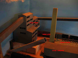
Getting the trackwork on the Coke Works Branch back up and running has inevitably led to getting back to work on the coke works itself.    The space that I am working with is pretty tight, ideally I'd like to have 4x16' to properly model a coke works - I have more like 2x4' .  It is at the end of the layout so the premise is, of course, that you are only seeing part of the actual plant.   
Part 1 was posted a long time ago and I'm not sure what description I gave of things at that point.  Basically, I have two main tracks going into the works - one for coke out and the other for coal in, with a very short spur to load by-products.    One thing that is a bit different from my usual faire, is that many of the structures in the coke works were kits or kitbashed structures.  Starting at the layout edge is a slightly modified Walther's New River Mining Structure - this is the coal receiving and prep buildings - it hides the edge of the layout and also covers where the two track main enters the backdrop.  This structure is meant to represent the center of the plant.  Also from this kit I used the separate hopper structure as a coke loader, raising it a bit and adding some walkways and stairs.   The coke is received here by conveyor, from an coke wharf and prep building not modeled  (past the end of the layout).   The next structure is a Walther's Gas Retort kit - the actual coke works kits had not been rereleased when I started working on this facility so I used what was available.  It only has a small number of actual coke ovens, but again, the idea is that there are many more on the other side of the plant.  This kit was built straight out of the box, but I will be adding rails and catenary to the top of the oven as well as the discharge platform side.  Because of space, the pusher side of the ovens is completely unmodeled.  I would have loved to model a pusher but this machine's traverse takes up a lot of real estate, of which I had none to spare.    I also have laid track in front of the ovens for the quench car and locomotive (both these were scratchbuilt and their construction described in earlier blogs).  This track extends to the edge of the layout where it enters a to be built quench tower (scratch) .  Not having the space to model the actual coke wharf (where the coke is dumped from the quencher), I've given the impression that it is on the other side of the plant.    Following the actual ovens I had intended to have the Walther's Gas Holder - this is an excellent kit, but it just barely fit between the tracks, not looking very prototypical, and it took up too much space,  that I decided could be better put to use as part of the by-products plant.   I still want to use this model but the only place close by would put it a dozen yards from the pig-caster, again, not very prototypical.   It might end up on the part of the layout yet to be built.   So basically without the gasholder, the remaining area between the ovens and where the track comes to a point will be the by-products plant.  One of the buildings in this area, the gas exhauster/ammonium sulphate building will be represented by a Walther's Vulcan Manufacturing structure - pretty much by the book except for closing in a few windows where piping will enter.   The remainder of the by-products plant will be mostly scratchbuilt.   Unfortunately, I again run short of space and I believe I will have to represent the benzol plant off-layout.   In the immediate future I intend to concentrate on some of the by-product structures and also the charging car and the door opening car - all will be in their own blog series ByProduct Plant,...etc.     When I start putting it all together and painting structures I will come back to this series.