Sunday, May 31, 2009

PIG CASTER Part 13


Over the weekend I worked on two elements still needed on the pig casting machine.  I started building the crane.  This is only partially necessary -  the prototype was located next to a blast furnace cast house and used large ladles to collect the hot iron and then the crane lifted and tilted the ladles.  My pig caster is receiving hot iron in bottle or ladle cars and thus technically there is nothing to lift, other than to maybe tilt a ladle.  Never the less I am still modeling the full crane, slightly modifying it for the ladle cars I am using.     The prototype drawings show limited details when it comes to the crane, so some of my modeling is freelanced in terms of exact layout,...etc.  

The crane frame was built using modified 1/4" I beams and 3/16" channel.  The wheels were made from sandwiches of punched circles with a brass axle.  Drivetrains and motors were made and installed in what I think are logical locations.  The main hoist sheaves are 43" grandt line parts.  

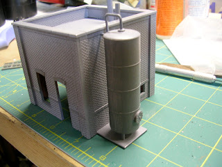
The other structure I worked on is a small brick building that will serve as an office, storeroom, pump house and winch house for the pig casting machine.   It was built using DPM modular components.


Tuesday, May 26, 2009

A-FURNACE PART 8


Spent tonight adding more rings to the stoves.  I'm up to 73 scale feet on each, just another 27 to go, but I've run out of Rix Tank kits once again.  Looks like I should only need two more 60' kits to do it.  If anyone needs 20 or so tank tops let me know.   I started thinking about the tuyeres for both furnaces.  Using Plastruct components will set me back almost $100 for both furnaces.  The Steel Mill CFO (my wife) has ordered across the board capital expenditure cuts due to four years of college tuition for my daughter starting in August.  
 Having more time than money I set out to mock up a prototype using Evergreen tubing.  I'm pretty happy with the results so far - a little more cleanup and two lift rings and I should be good.  It takes very little tubing so the total cost should be more like less than $20 for both furnaces.  Now to make 12 for A furnace and I think at least 18 for B (B-Furnace will have a slightly different configuration.   Maybe I'll pop in the 4hr Das Boot Director's Cut and get them done.  
A word on tubing and for that matter plastic structural shapes in general - I've found that the Evergreen shapes are much finer and hence thiner that the same sized Plastruct.   While looking more prototypical, some of the smaller H-columns made by Evergreen bend with very little weight on them.  On the other hand, the tubing, which Evergreen makes to 1/2" telescopes on 1/16" increments, which is an advantage.  It is also made of styrene so it glues better than the Plastruct.  Due to this, you will see me probably shift more toward Plastruct for my structural shapes, using Evergreen for my sheets, solids, and tubing.  

Monday, May 25, 2009

TEEMING LADLE Part 1


I think I might have spelled teeming, teaming, before, but then again I'm sure I misspelled a lot on here.  I posted a picture of this fine resin casting that I purchased from Brandon Wehe.  He manufactures this ladle, a charging ladle, a scrap bucket (which I also purchased) and scrap boxes.  I intend to eventually purchase a number of the charging and teeming ladles as well as a few scrap buckets.   The ladle is very well detailed and Brandon adds the trunnions and other fittings.  The only additional detailing that needs to be done to this is mechanism for opening and closing the plug in the bottom of the ladle.  Brandon includes a drawing of this and some suggestions.  I used the drawing and created this detail using a combination of plastic tubing, strip styrene, and brass 0-sized hex head bolts.  Oh, and a few Grandt Line NBW.   Looking at the picture I need to clean it up a bit and also add a piece of rod on each side of the lower pivot.  I am not 100% happy with the upper pivot bracket, but I'll improve this by using a smaller piece of tubing the next time.  
 If you are wondering how this works, basically, the operator, standing on a teeming platform, pivots the lever which in turn raises the arm on the outside of the ladle and also the inner arm that it is connected to.  This inner arm clears the hole in the bottom of the ladle, allowing the molten steel to pour into the ingot cars.   The one picture shows a real teeming ladle on display at Roebling Steel.  It is the ladle on the left, the other one is a scrap charging bucket.   You can clearly make out the mechanism, which is only slightly different than the one I built.  
By the way, I wish I knew exactly what sized pieces of plastic I used for this, but I was pulling stuff that looked about right from the bin of loose pieces.  If you really need to know email me and I'll measure and make a list.   Also, if you are looking to buy these ladles, Brandon Wehe's order form can be found on both the Yahoo Steel Group and the Steel Discussion Board I believe.  If you can't find it, email me or just post something on one of those boards as I believe he is on there on occasion.    This will be a short topic probably - Part 2 showing it painted.  

A-FURNACE PART 7


More work on the stoves, specifically the gas burner system.   In the last few blogs on this furnace I showed the construction of the gas burners.  Since then I have added a valve for each burner and the gas supply piping.  The piping for the most part is pretty accurate.  It goes from 5/16 diameter for the individual burner supplies, then to a 7/16 main for the three front stoves, then to a 5/8" riser, and then a 1/2" main, to another 5/8" riser (the wood part), and then finally to a 5/8" main (only partially modeled.   I did have trouble with the valves for each burner - the plans showed a valve that at first looked like a basic pipe valve but then it did look like it had a gate on it.  I'm trying not to get bogged down with issues like these so I followed the plans and made up what I couldn't see.  Each valve was built using a 5/16 pipe with a short section of 3/8" that I tapered the ends over top.  I then used 7/16 and 3/8" slices of pipe for the rings.  I then built a gate assembly and added some details to that.  I still need to add a hand wheel and chain (wire) to operate each valve.  

HEAT TREATMENT #3 - Part 3


I've started the long process of laminating brick sheets onto this structures core.  Unfortunately, I need to brick the interior also as it will be detailed.    The panels are being adhered with Elmers spray adhesive and then the seams glued with styrene cement.  I am fortunate that the exterior of this building had vertical exposed steel as it makes a good place to break the brick sheets.  I am a little concerned with the horizontal seams and how they will blend together.  You can see the holes in the bottom of the structure for the furnaces, assembly pit, and oil quench tank.
 

Spring Breezes


The good news is that after a much needed clean-up I have more space to assemble some of the larger structures, and after sending another dozen boxes back to my mom, we should be good to go on the final expansion of the layout - the main yard and either a city or additional steel mill structures.    The bad news (in a fashion) is that the warm air and spring breezes are drawing me out of my man cave and onto my sailboat.  I get to catch up on my reading and develop plans.  I am also excited to be based on the Chesapeake Bay this year.  I am hoping to sail over to Baltimore in the very near future to check out all the marine industrial archeology, especially Sparrows Point.  

Tuesday, May 19, 2009

PIG CASTER Part 12


I built railing for the stairwell.  As I have been doing for all my models now, I am building the railings from scratch.  The steps are Plastruct products but the railings are individual .030x.030 posts and .020x.040 railings. 

A-FURNACE PART 6


The four stove burners are complete.  Next I have to build the gas control valves that are just above the burners and then I can finish all the gas piping.  
I continue to add sections to the stoves.  I need to hit about 100 scale feet to finish.  It's a slower process than the other models where I have used the Rix sections.    Wish I had more to show at this point but I spent a good part of the weekend cleaning up down in the basement.  I was getting to the point were there were just piles everywhere.  I was able to get about twenty boxes of my wife's craft stuff out of there and up to her third floor studio.  In the process I gained a third workbench, which was sorely needed.   On the new workbench I set up linear storage bins for all the plastic components that I work with.   I also pulled a bunch of boxes that I was storing for my mom and brought them back to her house.  Once I remove the remainder of those I will be able to start building the benchwork for the final 4'x14' layout section.  It is to be the main yard and either a city terminal or I might let steel creep into this section as I have no room for my open hearths anywhere.  In either case it will have a yard.  

Tuesday, May 12, 2009

PRECIPITATOR Part 1


I Started some basic construction and planing on these.  Once again using Rix Water Tank pieces.  In the case of these units, the 24' diameter scales out perfectly.   There are two precipitators, each one needs to be 3 Rix pieces high, but one of each size.  I need to pick up a few more tank kits, specifically the 60 footers as they are the only ones with the larger sized plates.  
A precipitator is used as the final step in cleaning the used blast furnace gas.  It uses electrostatic to extract the fine particles of dust from the gas.   I am once again modeling the units found at Bethlehem Steel.   They were located behind A-Furnace - I will be placing them at the exact prototype location.   At Bethlehem, A and B furnace shared these precipitators - this makes for some interesting piping arrangements.    According to the drawings, other furnaces could also use these units, although I'm not sure how many (Bethlehem had five furnaces in the 1950's.   You can see the precipitators in the black and white photo just to the left of the stone building.  

A-FURNACE PART 5


Stove Burners - These heat the stoves and are fueled by clean blast furnace gas.  There is one per stove.  The drawings don't show much detail on these other than a basic shape.  I was lucky to find a close up photo on the internet showing the burner.  There is quite a bit of detail on these.  I was thinking of carefully replicating one unit and then making a mold and casting additional pieces, however, the shape of them would be difficult to mold well.  I have opted to make each one individually with some simplification, but still enough detail.  They are built from styrene tubing - mostly 5/16 but with some of other sizes.  

HEAT TREATMENT #3 - Part 2


The basic walls of this building were cut from 1/4"MDF  and assembled.  The window openings are rough cut a little larger than what I actually need.  Now comes the long process of veneering the building and building all those windows.  
The building will be actually a bit higher as there is probably another 20' of wall plus the roof trusses.  This was not brick and was just steel framing and corrugated steel.  I will be leaving the back off the building and detailing the interior.   Both of the side bays are supposed to be the same sized, but due to space constraints I needed to sacrifice one of them.  I chose the side that houses the winch as from what I could tell there was no other major machinery inside this room and the winch occupied the first half.

Friday, May 8, 2009

HIGH LINE Part 3


On and on with this structure.  Just a lot of production line modeling.  A few photos so you can see some of the process.
1.  Cut .040 styrene into large pieces - some for the large sides and some for the inner sides.  I use a NWSL Duplicutter for this.
2.  Using a template, trace out the large sides.  
3.  Cut and piece in the inner sides - 5 pieces total
4.  Use a strip of 1/8" (.125) to draw the set back lines on the large sides, outside edge.
5.  Glue up hopper assembly.
6.  Glue two hopper assemblies back to back
7.  Build large I-beam from a scale 39' long strip of .040 styrene - I use a General HO Ruler as the width.  Apply .030x.188 strip plastic to create the flanges
8.  Glue the beam to the side of the hopper/bin assembly
9.  Cut two legs from 3/16 H Column - install one at back edge and one set back 1.25 inches.  Cut a square piece of .060 plastic as the pad for the front leg (.250x.250) and then a strip of .250 for the rear.
You will notice if you have a set of these plans that I am taking a liberty and reversing the high-line assembly so that the side with the set back legs and interesting detail is up against the stoves and furnace.

A-FURNACE PART 4


I was starting to feel I was neglecting A-Furnace - first I stole it's stoves to use for B-Furnace and then I haven't really done any work on it for some time.   This furnace is the most challenging of most of my projects as I am trying to stay true to the prototype.   
I think I wrote before about the issues with the diameters of the various stoves and adapting the Rix Water Tanks to use for these various sizes.   The A-Furnace stoves are 22 feet in diameter.  This means that I need to use 5.5 sections to go from the 24' using 6 sections to the 22' needed.  The stoves are built on a piece of .080 styrene.

Wednesday, May 6, 2009

HIGH LINE Part 2


I finished a few more bins tonight.  I have built a total of 10, the entire high-line will have 60.  You will notice that two of the bins are smaller than the others.  This is for the skip hoist from A-Furnace.  I've added some of the upper beams.  There are four more to be installed under the rails.  I have decided to stick only to standard gauge on both tracks.  I put the high-line assembly temporarily in place with a mock up of one of the skip hoists.  There is still a ton of work to do but I can envision the area and with the stoves, the hoists, the high-line, piping,...etc.  its going to look awesome.  

Tuesday, May 5, 2009

HIGH LINE Part 1


I haven't been doing a whole lot of modeling for a week or so - I've been under the weather and then my teenage daughter needed emergency surgery.  Tonight she returned home, doing fine but in some pain, and I'm just starting to get over my sinus cold.  It was also the first night in a while that I felt like going down to my workbench and modeling.  I shift gears a little and started work on the high-line.  For you non-steel people, the high-line is basically an elevated railroad used to fill many separate storage bins located beneath the high line with the essentials for fueling blast furnaces - iron ore, coke, and limestone.  Under these bins is a sunken railroad track that has a scale car on it.  This scale car receives materials from the bins and transports them to the skip hoist and thence into the blast furnace.   I will be modeling pretty closely the prototype high-line used at Bethlehem Steel.  On this line, the inner track is standard gauge and the outer is dual gauge (standard and 5')   The wide gauge track was used for special cars used to transport the ore at Bethlehem.   I am not sure if I am going to model dual gauge or just stick with standard on both tracks.  I also won't be modeling the scale cars or line under the high-line.    What you see is the first four, of very many bins that will make up my high-line.  The bins are made of .040 styrene with wide flange beams between (3/16x 1) supported by 3/16 H-Columns.   The structure still needs a framework to carry the rails, made from 5/16 I-beams.