Wednesday, February 24, 2010

PRECIPITATORS Part 10


Added two more pipe/valve combos to the clean gas manifold.  Fabricated  pipes for the other side (dirty gas).    These input lines actually split into two smaller pipes each before entering  the precipitators.  

Monday, February 22, 2010

PRECIPITATOR Part 9


Tonight I started installing the gas piping on the precipitators.  Since there are two precipitators and each one has two inputs for dirty gas and two outputs for clean gas, there are four basic piping arrangements involved, so I will build them two at a time, for consistency.  I choose the easiest arrangement to begin with - it is the clean gas off take that runs perpendicular to the clean gas manifold, turning into the top of the precipitator.  Despite this straight run, there are a number of pieces and compound angles involved.   I assemble the curves first, from small pieces of 3/4" tubing cut on opposing 11 degree angles.  I then held them loosely in place and measured for the horizontal return to the manifold, and cut it.  Then, holding this assembly level, I guesstimated what was needed for the return piece from the curve to the top of the precipitator.  This piece will need some sanding to get it to fit just right.  I then assembled the Alkem Scale Models goggle valve kit onto the end of the horizontal pipe .  The whole assembly was then glued in place.   Next - the remaining two discharge pipes. 

Sunday, February 21, 2010

PrECIPITATOR Part 8


In order to start fitting the piping and the new goggle valves to the precipitators I needed to do some finish up work on them at the bench.  I needed to finish the ladder cages on one, add the top railings to both, and add a few access hatches.   After this I mounted the units to their base, between the dirty gas and clean gas mains.

Narrow Gauge - Part 7


Some news on the continuing quest for narrow gauge locomotives and equipment for the as yet built steel making section of the layout.   The Grandt Line 25 tonner that I built earlier in this blog looks great, but is technically challenging to build and runs, well runs like sh*t, even filled to the gills with lead.   On top of all that I had to carefully re-gauge the Grandt Line wheelsets from HOn3 to HOn30.  There are a number of real good inexpensive N-scale mechanisms out there - the Bachmann MDT is $20 and runs smooth (its a six wheeler) - moving up to two trucks, their 44 Tonner is a real good runner.   I could probably get the Grandt Line body to fit on the MDT power unit, but I don't really feel like paying $50 for a body that I have to assemble.   Funaro and Camerlengo make a few different inexpensive narrow gauge switcher bodies in HO - they are are designed to be used as freight car loads and haven't really been designed to be motorized.   My first attempt to use the Plymouth Body with the MDT didn't work out as the hood was too narrow for the mechanism.  This weekend I came across a new issue from them - a Cat Diesel Switcher.  I was able to get the MDT to fit this shell, although I had to cut down the hood and also grind a little bit away of the inside corners - I will build a step or a tool box to cover this.  I've also discovered that I will be able to use the Plymouth body with the Bachmann 44 tonner mechanism - but Ill need another body kit to modify it into a two hooder.  

Wednesday, February 17, 2010

PRECIPITATOR Part 7


In lieu of scratchbuilding the eight goggle valves that I need for the precipitator complex, I am trying the new laser cut acrylic and cardstock kit from Alkem Scale Models.   These kits run about $10 a piece and I had a bit of internal debate over whether to buy them or stick to scratchbuilding.  The design of  the Alkem valve is a bit different than the prototype at Bethlehem, however, my overriding concerns were speed in building, so as not to get too bored building this element of the steel mill, and consistency, as the valves will be close to each other - they need to look identical.  If I held the three valves that I already built elsewhere in the mill, there would be subtle but noticeable variations in each one.   I also liked the delicate gear teeth on the curved rack drive of the Alkem valve.    I still haven't worked out all the details but I will need to make some modifications.  I will need to add internal .030 shims to the valve pieces so it will fit tight on plastruct TB-24.  These shims are visible in the one photo - they are just a .030x.100 strip of styrene curved to fit the inside of the valve components.    The other area of modification will be the drive mechanisms.  I will probably deviate from the plans on this, but just don't know exactly how yet.

By-PRODUCTS PLANT Part - 12


The photo shows the start of construction of the final cooler/benzol washers.  I used a thin wall PVC pipe for the cooling towers - it scales out at about 12' diameter - pretty close to the prototype.  I scribed panel lines on all three towers and started the install of the recessed tops and walkway.   I used a fair amount of this type of pipe in the construction of the modern pipe foundry.  It is much less expensive than Plastruct, but doesn't take the glues as well and it retains a lot of static energy, especially in the dry winter air.   

Sunday, February 7, 2010

A-FURNACE PART 27


A fellow steel mill modeler commenting on my blog awhile ago said - "I can't wait to see how you do those uptakes".   That was actually my feeling on them too, and the reason that I am just getting around to them now.    Trapped in the house for a snowy weekend, it seemed like a good time to start thinking about the upper works of my A-Furnace.    Most of the uptake assembly boils down to a lot of pipes connecting at many different angles - but there are two very complicated steps that are part of the assembly - the intersection of the two lower uptakes, and the connection from the furnace body to the uptakes.     
The intersection is more complicated than most other scratchbuilt furnaces I have seen.  Bethlehem Steel elected to do some real fancy sheetmetal work at this intersection as evidenced by the prototype photo.   Besides the weird mess at the intersection,  the upper part of the intersection is actually transitioning from one diameter pipe to a larger one, just to make things a bit more interesting.  In my model, the lower uptakes are 3/4" Plastruct tubing - this will transition into 7/8" tubing, and then transition to 1/2" for the bleeders.  Additionally, more 7/8" pipe with come off the uptake and meet at the 1" downcomer.  I've worked out a plan to accomplish all this - it won't be easy, but it should work with a little patience and care in shaping the parts.   
The second problem is that, also unlike most model furnaces, the Bethlehem Steel prototype that I am using had uptakes that started to angle back in two segments to the furnace body - above the deck of the charging platform.  It is much easier if the cut back starts right at the charging deck.  Building it this was allow you to attach the piping and center it up on the deck as you build the upper works.  After much thinking I elected to cheat a bit here and deviate from the prototype for the sake of streamline construction.   I probably won't be noticeable to anyone that hasn't spent hours studying the Beth Steel A-Furnace plans.  
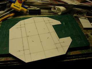
So, the easy work is done - the deck was cut from .040 styrene and 1/8" i beams and square strip were added under.  The uptakes were cut from 3/4" tubing and assembled up to the intersection.   The next post will take us past there and on up toward the downcomer.  

Saturday, February 6, 2010

By-PRODUCTS PLANT Part - 11


I added some water piping to the front of the primary coolers.  I'm not sure these pipes are discharge or intake lines, but they are prototypically correct according to the photo that I am working off.   I suspect they might be the discharge lines with some sort of trap or level arrangement evident.   The smaller pipes are 1/8"  tubes and the larger, 5/32".  I made the tees and flanges on the larger sized piping, but with the 1/8" tubes, I used cast flanges, tees, and elbows, from Bollinger Edgerly Scale Trains, or BEST.     Originally I had planned on using some Walther's products - the piping detail kit for the refinery - however, the detail of the flanges wasn't very well done, and the tees were oversized.    Unfortunately, I ran out of the BEST flanges so I was unable to complete the piping details.  I will have to order some more.