 |
| The raw material.... |
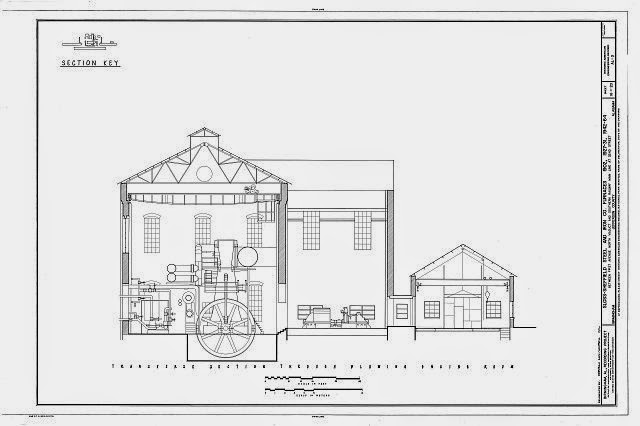
I finally had some time to play around with the Silhouette Cameo a little today. As I mentioned in the previous blog entry, I intended to try out cutting a roof truss for large industrial buildings. The Cameo cutting area is 12"x12" so you could do almost any truss for an industrial building, and could maybe even layout diagonally if you needed an inch or two more. My original plan was to draw this in the free drawing program that Silhouette puts out - Silhouette Studio v.3, however, after some playing around with the Trace feature of the program, I tried using an existing graphic as the basis to make things a bit easier. A quick search of HAER documentations I quickly picked the above drawing of the Sloss Furnace blowing engine house. I downloaded the highest resolution TIFF drawing and cropped the top portion of the drawing. The truss on this building is about 72 feet wide - perfect for HO steel mill buildings.

The next step is to use the Merge function in Silhouette Studio to import this image. This is the image merged onto the 12"x12" cutting mat background.
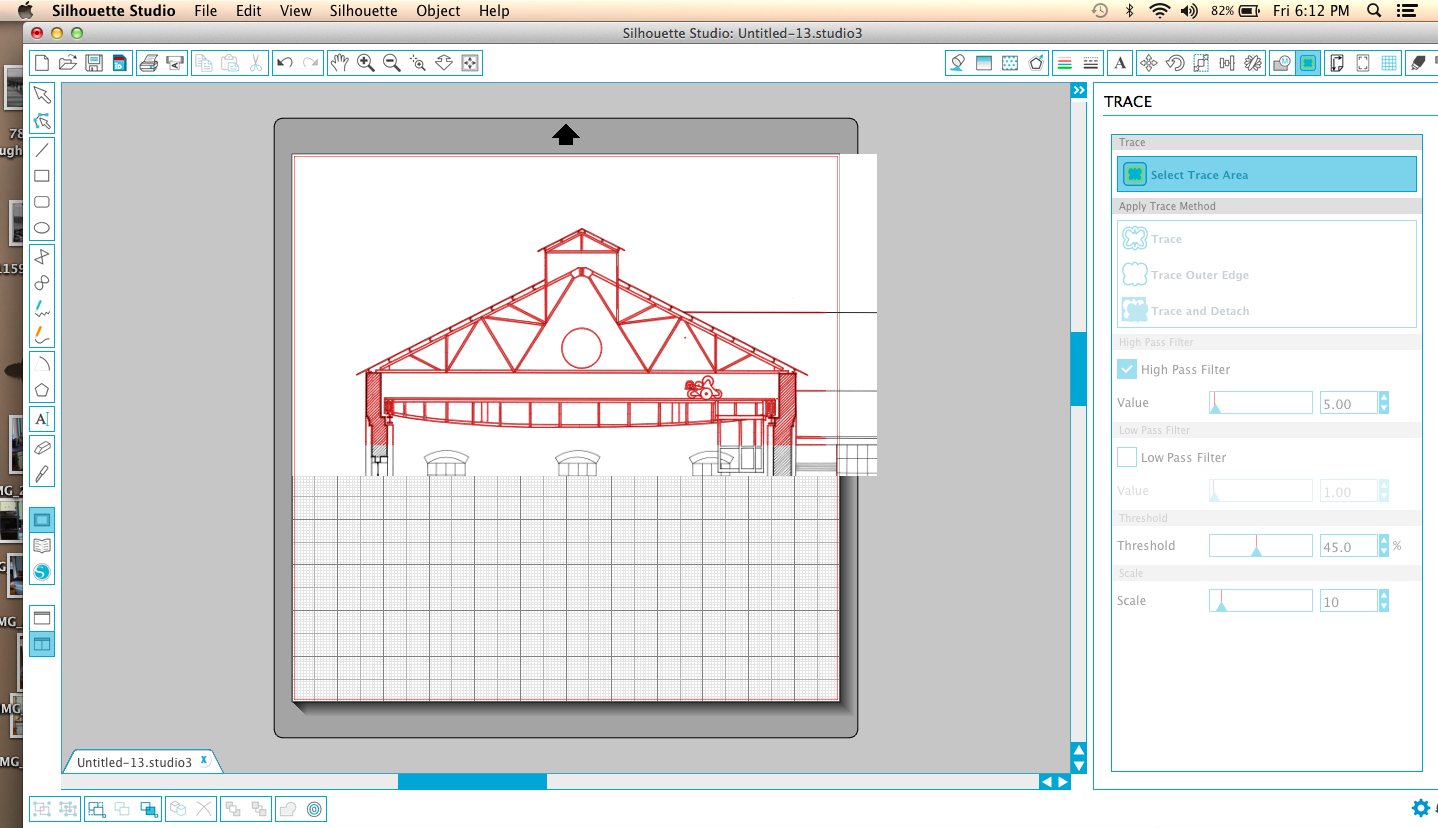 |
| Trace Function |
Now use the Trace function to "trace" the image. The red lines are the actual cut lines that the machine would cut into your material. The black lines of the original image wouldn't be cut, however, you could print out them first on your regular printer and then feed that print into the Cameo and it would cut along the red. This would be useful in paper modeling, but you can't feed plastic into your printer. It would be nice if it were this easy, but the trace function is imperfect. There are filters and other variables to adjust the Trace function that might improve the result, but this was what seemed to work well. Besides the walls and crane that I don't want to cut, if you zoom in, and you can zoom in quite a bit (something that is useful in cleaning up the cut image) you will see the computer literally traced all the lines - the truss members are two lines, but the red cut lines placed by the Trace function are on both sides of each line, so there are four cut lines - it literally traced the black lines as if they were images. You need to clean up the drawing. It's some work, but not as much as drawing from scratch. There is an eraser tool which helps with a lot of the extra images but be careful within the lines themselves. If you are using the erase tool it's best to zoom in all the way as you will have more precise control. Easier yet, is to use the Select pointer tool to select lines and then click delete. This method is faster and cleaner, however, you need to make sure what you select isn't attached to the larger image and deletes more than you want. If you do, you can always use the Undo tool in the Edit menu to take a step (or five) back. You will also find that you will need to fill in a few places with new lines. Use the Line tool in basically a connect the dots fashion. You can also adjust the lines if a little off by clicking on them with the select pointer and change the angle or length. The idea is to make sure you have continuous cut lines all the way around so you won't have to cut your parts out. Also, make sure to erase all intersecting lines so the part is all one piece. One interesting problem is that the original Sloss drawings were hand drawn by a human (pre-CAD documentation) so when you zoom in, slight human errors in the lines become more pronounced. I cleaned up a few but left others as these errors are relatively small and not noticeable.
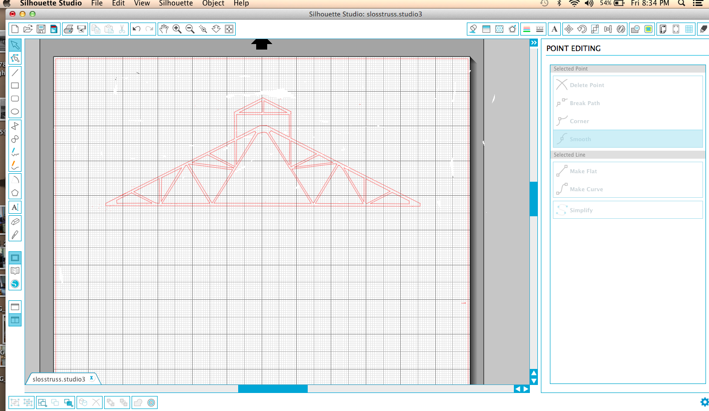 |
| Final cut drawing |
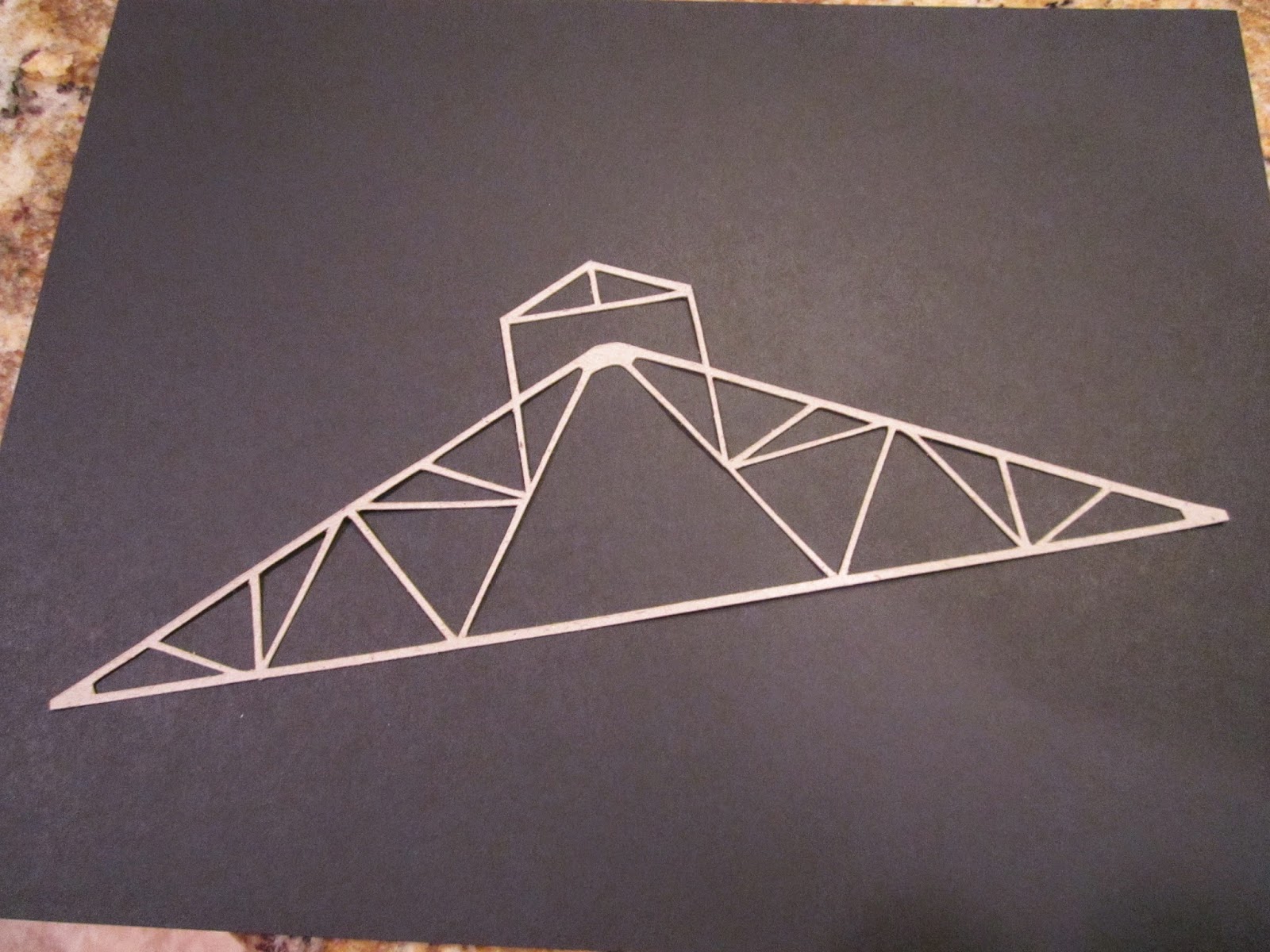
I'm out of .010 plastic so I did a test cut in cardboard stock. It's easy to copy the entire truss so ultimately this file will have two or three more trusses to fill the page. Once I get some plastic (tomorrow) I will play around with some options on actual construction. My plan now is to use this as the core for the truss and just cut and glue on strip styrene or angles to stiffen and give the truss depth. I'm very happy with the results. I will probably use these trusses for the roof of my to be built rod mill. After I publish this entry I'm actually going to cut another truss or two and explore using the cardboard (it's called chipboard by Silhouette) as the truss - laminating them. Just an idea.
2 comments:
Very interesting!
Really cool Jim. Love all your work and thanks for taking the time to describe it in such detail. Hope to see you at itimonium again someday. -art m
Post a Comment